QIACHIP TX183-4 Instruction Manual DC 3V-24V 433MHz RF Transmitter Module
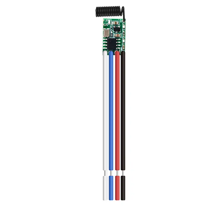
Version: V1.0
Last Updated: 2026-08-17
Model: TX183-4
Product Size
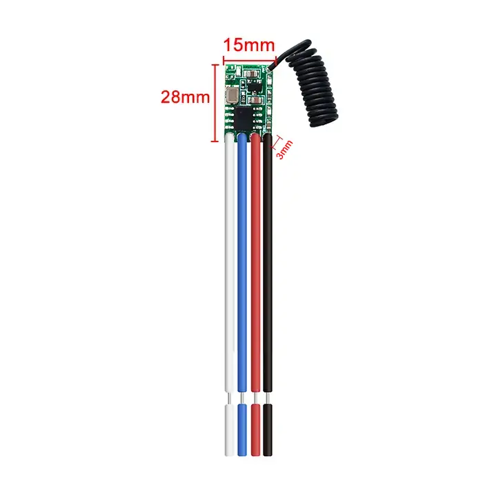
- Length (L) x Width (W) x Height (H): 28mm x 15mm x 3mm
Component Description
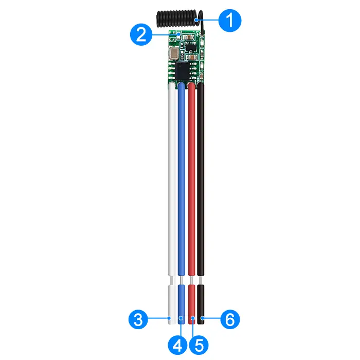
- 1: Antenna
- 2: Indicator LED
- 3: K2 (K2 trigger input; connect to GND to transmit the K2 code)
- 4: K1 (K1 trigger input; connect to GND to transmit the K1 code)
- 5: V+ (Positive power-supply input)
- 6: GND (Negative power-supply input)
Wiring Diagram
Disconnect power before wiring.
Figure 1
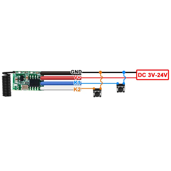
Figure 1: Wiring diagram for external button connections
- Input Power: DC 3V-24V
- After the module is powered on, pressing the external button will turn on the Indicator LED and make it transmit signals.
- When the external button is released, the Indicator LED turns off and signal transmission stops.
Electrical characteristics
| Parameter | Value |
|---|---|
| Input voltage | DC 3V-24V |
| RF frequency | 433.92 MHz |
| Encoding protocol | EV1527 learning code |
| Transmit power | ≥ 10 dBm |
| Transmission range | 20-80 m (open, unobstructed environment; actual range varies with operating conditions) |
| Quiescent current | 0.1 mA |
| Working temperature | -40 °C to +85 °C |
| Size | 28x15x3mm |
Warning
- This module contains ESD-sensitive CMOS components. Observe appropriate ESD precautions during storage, transportation, installation, and operation.
- Connect GND securely to the negative terminal of the power supply before applying power.