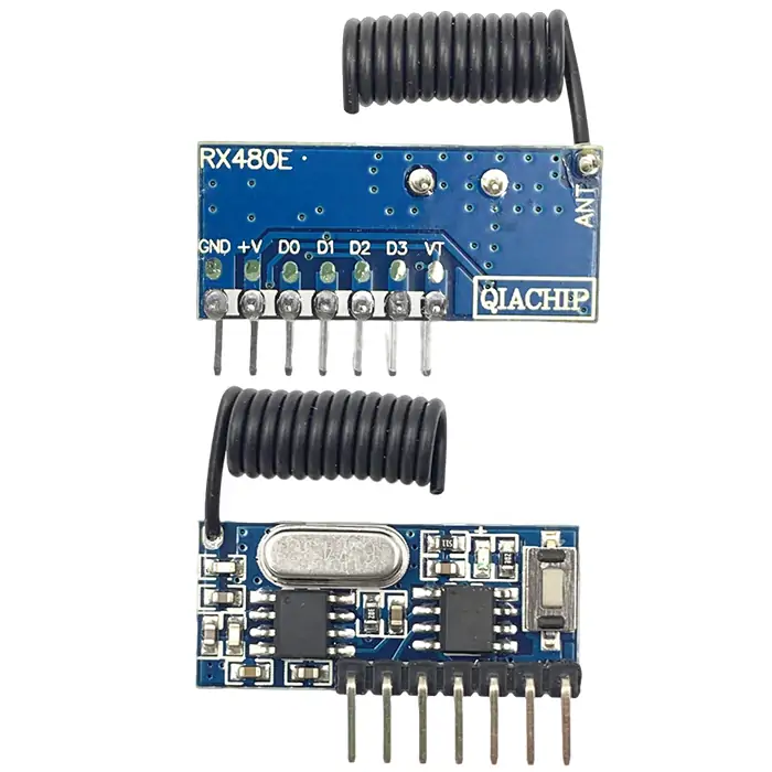
QIACHIP RX480E-4 ( RX480E Series ) Instruction Manual DC 3V-5V 433MHz RF Decoding Wireless Receiver Module
Version: V1.0
Last Updated: 2026-5-27
Model: RX480E-4 ( RX480E Series )
Product Size
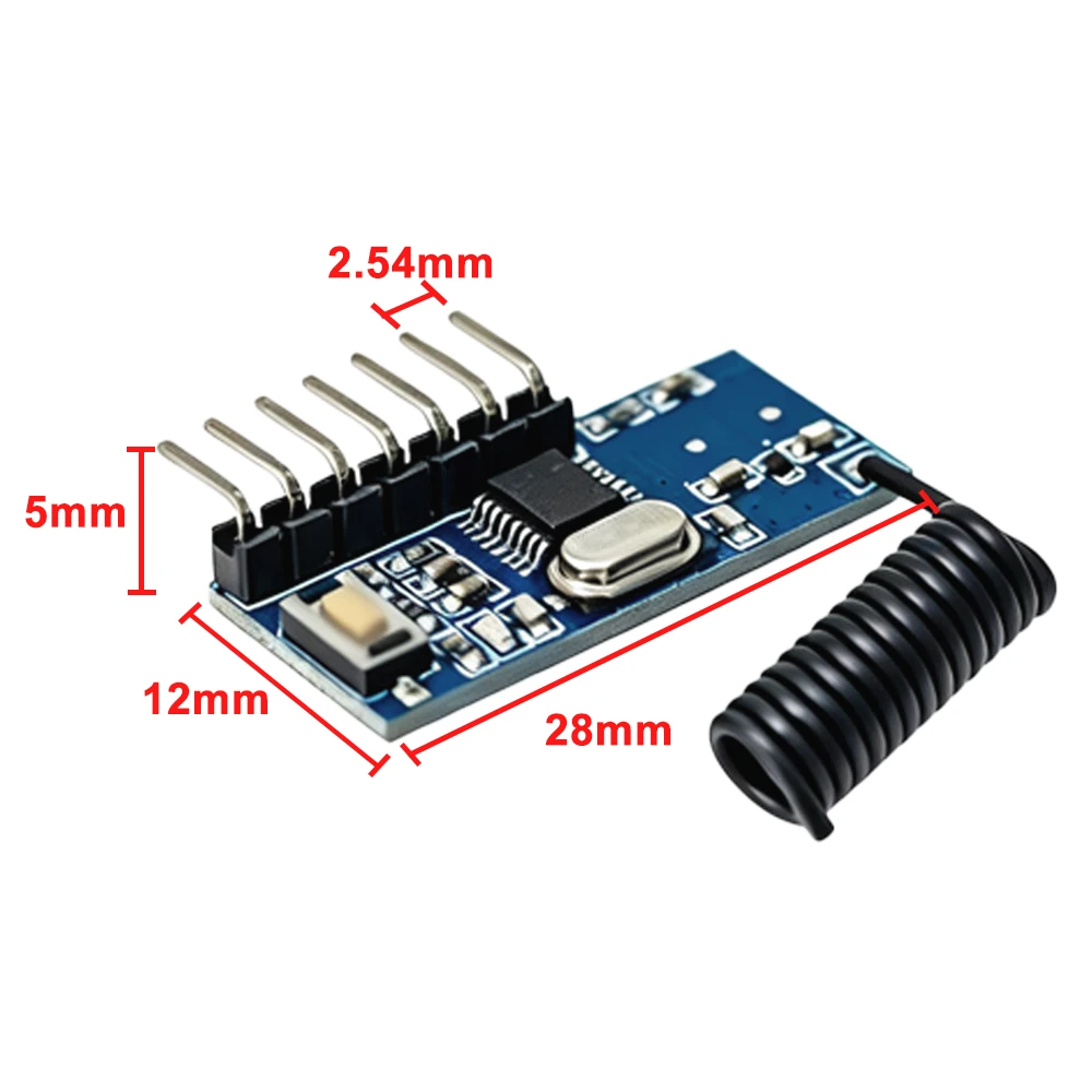
- Receiver Length (L) x Width (W) x Height (H): 28mm x 12mm x 1mm
- Receiver Pin header pitch: 2.5 mm
Component Description
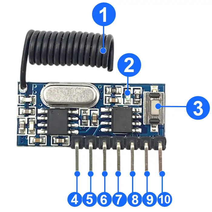
- 1: Antenna
- 2: Indicator light
- 3: Learning button
- 4: VT (External Key Input Pin)
- 5: D3 Signal output pin corresponds to remote control button value 8 (1000)
- 6: D2 Signal output pin corresponds to remote control button value 4 (0100)
- 7: D1 Signal output pin corresponds to remote control button value 2 (0010)
- 8: D0 Signal output pin corresponds to remote control button value 1 (0001)
- 9: V+ (Positive Power Input Pin)
- 10: GND- (Power Ground Pin)
Wiring Diagram
Disconnect power before wiring.
Figure 1
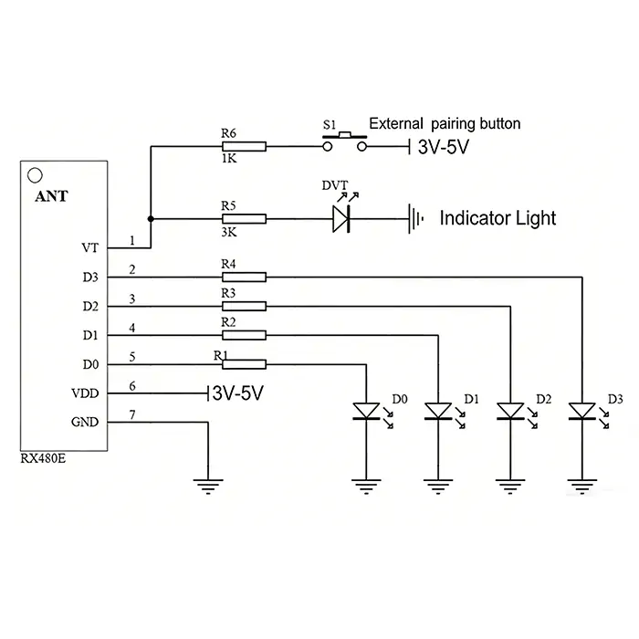
Figure 1: Wiring diagram for LED circuit
- Load: LED
- Input Power: DC 3V-5V
Function description and setting method
(1) Momentary mode; (2) Toggle mode; (3) Latching mode; (4) Reset function;
- The remote control with key value 8421 is used by default for mode setting as described in this manual.
- When using the third working mode, a transmitter with at least two buttons is required.
- Once the receiving module and transmitter are paired and a working mode is set, the receiving module will keep this mode even after power off and power on again.
- The following working modes require the use of QIACHIP brand remote controls (transmitters) and controllers (receiving modules/wireless remote control switches). Compatibility with other brands is not guaranteed.
(1) Momentary mode
In this mode:
- Press and hold the remote control button with key value 8, and the D3 pin on the receiver module will output a high-level signal "1".
- Release the remote control button with key value 8, and the output signal on D3 pin of the receiver module will change to "0".
How to set momentary mode
Step 1
Click the learning button on the receiver module once. The LED indicator on the receiver module will flash and then stay on, indicating that the receiver has entered pairing mode.
Step 2
Press any button on the remote control once. The LED indicator on the receiver module will flash and then turn off, indicating that the momentary mode has been successfully set.
(2) Toggle mode
In this mode:
- Press the remote control button with key value 8 once, and the D3 pin on the receiver module will continuously output a high-level signal "1".
- Press the remote control button with key value 8 again, and the output signal on the D3 pin of the receiver module will change to "0".
How to set toggle mode
Step 1
Click the learning button on the receiver module twice. The LED indicator on the receiver module will flash and then stay on, indicating that the receiver has entered pairing mode.
Step 2
Press any button on the remote control once. The LED indicator on the receiver module will flash continuously and then turn off, indicating that the toggle mode has been successfully set.
(3) Latching mode
In this mode:
- Press the remote control button with key value 8, and pin D3 of the receiver module will continuously output a high-level signal "1".
- Press the remote control button with key value 4, and the output signal of pin D3 of the receiver module will change to "0", then pin D2 of the receiver module will continuously output a high-level signal "1".
How to set latching mode
Step 1
Click the learning button on the receiver module three times. The LED indicator on the receiver module will flash and then stay on, indicating that the receiver has entered pairing mode.
Step 2
Press any button on the remote control once. The LED indicator on the receiver module will flash and then remain on, indicating that the latched mode has been successfully set.
(4) Reset function
When the RX480E-4 receiver module is reset, all paired transmitters will be unpaired and will no longer be able to control the receiver module.
How to reset
Click the learning button on the receiver module 8 times. The indicator light will flash and then will turn off. The reset will be complete.
Antenna Size
General Application Type
For general applications, you can directly use the market-standard specifications for the antenna. Details of the 433MHz antenna are as follows:
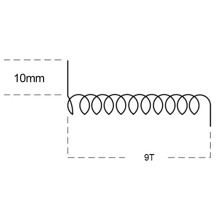
- Wire length at the soldering end: 10mm
- Total straight length of the antenna wire: 170mm
- Number of winding turns: 9 turns
Special Enhanced Type
If a longer communication distance is required and the general application type antenna cannot meet the demand, an enhanced type antenna can be used to improve the receiving distance. Details of the 433MHz antenna are as follows:
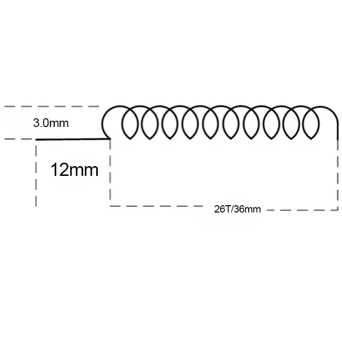
- Antenna core diameter (including outer sheath): 1.0 mm
- Antenna core diameter (excluding outer sheath): 0.35 mm
- Wire length at the soldering end: 12 mm
- Antenna winding diameter (excluding outer sheath): 3.0 mm
- Number of winding turns: 26 turns
- Winding length: 36 mm
Electrical characteristics
| Parameter | Value |
|---|---|
| Input voltage | DC 3V-5V |
| RF frequency | 433.92MHz |
| Power Consumption | 5mA |
| Receiver sensitivity | -108dBm |
| Working temperature | -42℃~85℃ |
| Size | 28x12x1mm |
NOTE
- This product is a CMOS device. Please take anti-static precautions during storage, transportation and operation.
- Ensure proper grounding when using the device.
- RF devices are voltage-sensitive. If the power supply is unstable or has significant ripple, add filtering at the power input terminal to ensure the supply voltage does not exceed the product's maximum operating voltage.
Frequently Asked Questions (Q&A)
Question 1: Can each of the four RX480E-4 output pins be set to a different mode, such as D3 in Momentary mode and D2 in Toggle mode?
Answer:
No. You cannot set each output pin to its own mode. However, you can choose one of these working modes:
- Reset the module: Press the Learning button 8 times
- Momentary mode: Press the Learning button 1 time
- Toggle mode: Press the Learning button 2 times
- Latching mode: Press the Learning button 3 times
- Two Toggle channels + two Momentary channels: Press the Learning button 4 times
- Two Latching channels + two Momentary channels: Press the Learning button 5 times
- Two Latching channels + two Toggle channels: Press the Learning button 6 times
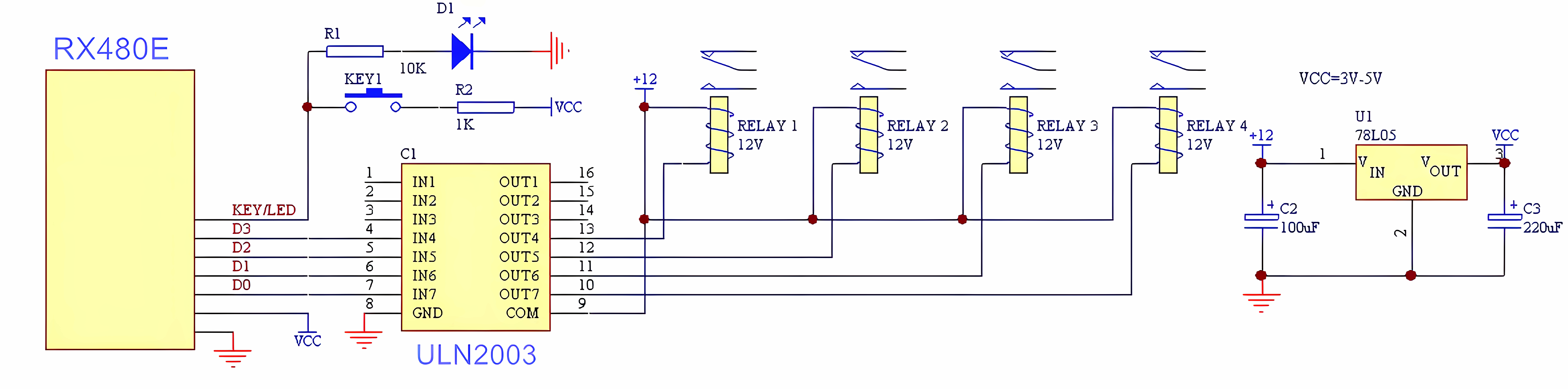
Question 2: Can the four RX480E-4 outputs drive a load directly? How to connect the four outputs to an external transistor or relay?
Answer:
We do not recommend connecting the four RX480E-4 outputs to a load directly. They provide high-level signals, and the maximum output current is 10 mA.
The four outputs need a transistor to increase the current before driving a relay, motor, or other load. This wiring requires basic circuit design knowledge. You can also follow our wiring diagram directly.
Question 3: Do I need to pair the transmitter and receiver again after a long power outage?
Answer:
No. Once the transmitter and receiver are paired, they do not need to be paired again after a power outage.
Question 4: Are the four outputs of RX480E-4 high-level or low-level outputs?
Answer:
All four outputs of the RX480E-4 are high-level outputs.
If you need low-level output, add a transistor inverting circuit after the four outputs. This wiring requires basic circuit design knowledge.
Question 5: Why can't I change the working modes after connecting an external button and LED to the VT pin?
Answer:
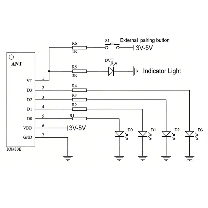
The wiring may be wrong. Follow our wiring diagram.
Connect a current-limiting resistor in series with the external LED. Otherwise, the VT pin voltage will be too low. When the VT pin voltage is too low, the module cannot change working modes.
Question 6: Is Momentary mode the factory default output mode for RX480E-4?
Answer:
No. RX480E-4 has no factory default mode. Choose the mode you need. You can find the pairing steps in the Function description and setting method section above.
Question 7: Does the RX480E-4 receiver support EV1527 encoding? Can it pair with other EV1527 remote controls?
Answer:
Yes. The RX480E-4 receiver uses EV1527 learning code. Pair the remote control and receiver once before use.
We recommend QIACHIP remotes. We do not guarantee pairing compatibility with other-brand remotes.