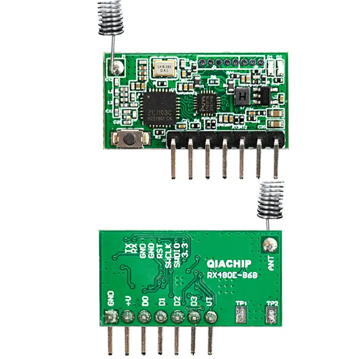
QIACHIP RX480E-868 ( RX480E Series ) Instruction Manual DC 5V-24V 868MHz RF Wireless Encoding & Decoding Transceiver Module
Version: V1.0
Last Updated: 2026-2-27
Model: RX480E-868 ( RX480E Series )
Product Size
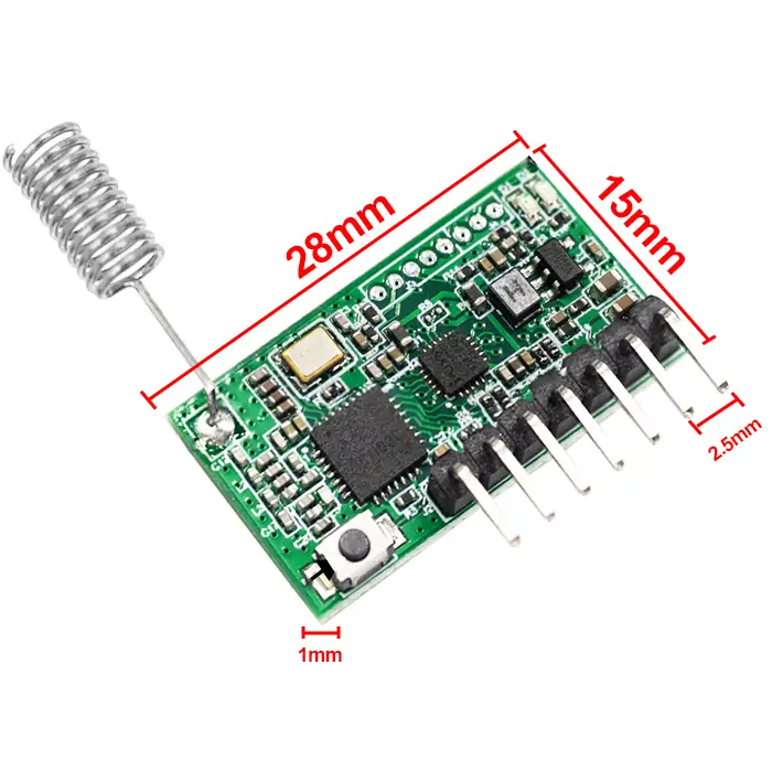
- Receiver Length (L) x Width (W) x Height (H): 30mm x 9.5mm x 1mm
- Receiver Pin header pitch: 2.5 mm
Component Description
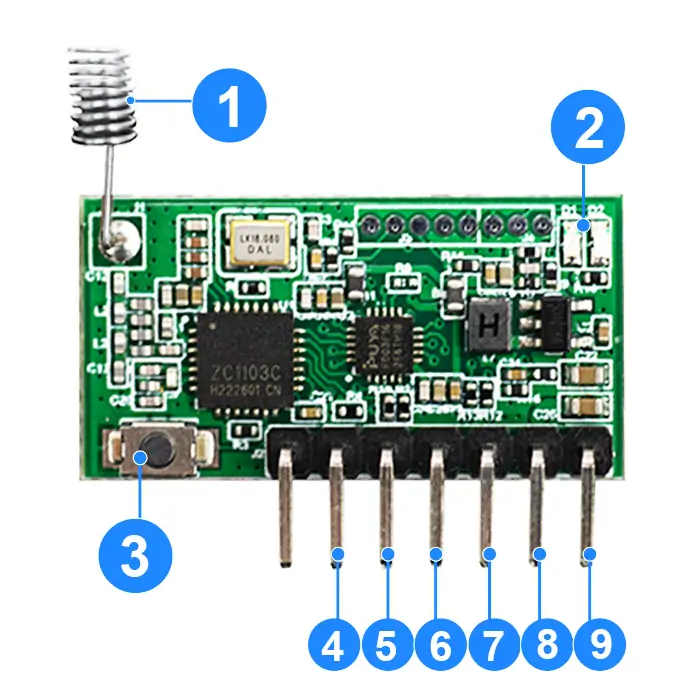
Default: Receive mode
| No. | Name | Type | Description |
|---|---|---|---|
| 1 | Antenna | - | - |
| 2 | Indicator light | - | - |
| 3 | Learning button | - | - |
| 4 | D3 | IO | High-level signal output, pin corresponding to D3 in transmit mode |
| 5 | D2 | IO | High-level signal output, pin corresponding to D2 in transmit mode |
| 6 | D1 | IO | High-level signal output, pin corresponding to D1 in transmit mode |
| 7 | D0 | IO | High-level signal output, pin corresponding to D0 in transmit mode |
| 8 | +V | P | Power supply positive input (5V-24V) |
| 9 | GND | P | Power supply negative input |
Transmission mode
| No. | Name | Type | Description |
|---|---|---|---|
| 1 | Antenna | - | - |
| 2 | Indicator light | - | - |
| 3 | Learning button | - | - |
| 4 | D3 | IO | Low-level signal input, pin corresponding to D3 in receive mode |
| 5 | D2 | IO | Low-level signal input, pin corresponding to D2 in receive mode |
| 6 | D1 | IO | Low-level signal input, pin corresponding to D1 in receive mode |
| 7 | D0 | IO | Low-level signal input, pin corresponding to D0 in receive mode |
| 8 | +V | P | Power supply positive input (5V-24V) |
| 9 | GND | P | Power supply negative input |
Function description and setting method
Receive mode
When the module is powered on, the red and blue indicators light up for configuration. The indicators turn off when configuration is complete.
- Two flashes of the red indicator indicate Receive mode.
- Two flashes of the blue indicator indicate Transmit mode.
(1) Momentary mode; (2) Toggle mode; (3) Latching mode; (4) Reset function.
- Once the receiving module and transmitter are paired and a working mode is set, the receiving module will keep this mode even after power off and power on again.
- The following working modes require the use of QIACHIP brand remote controls (transmitters) and controllers (receiving modules/wireless remote control switches). Compatibility with other brands is not guaranteed.
(1) Momentary mode
In this mode:
- Press and hold the button on the paired transmitter, and the corresponding output pin on the receiver module will output a high level.
- Release the button, and the corresponding output pin on the receiver module will switch to a low level.
- Each time the receiver module receives a signal, the transmitter will receive a feedback signal, and the blue indicator on the transmitter will flash 3 times and then turn off.
How to set momentary mode
Step 1
Click the learning button on the receiver module once. The red indicator on the receiver module will flash once and then stay on, and the receiver module will enter the pairing state
Step 2
Press the button on the transmitter to be paired. If the red indicator on the receiver module flashes 5 times, the pairing is successful.
(2) Toggle mode
In this mode:
- Press the button on the paired transmitter once, and the corresponding output pin on the receiver module will output a high level and hold it.
- Press the same button again, and the corresponding output pin on the receiver module will switch to a low level.
- Each time the receiver module receives a signal, the transmitter will receive a feedback signal, and the blue indicator on the transmitter will flash 3 times and then turn off.
How to set toggle mode
Step 1
Click the learning button on the receiver module twice. The red indicator on the receiver module will stay on, and the receiver module will enter the pairing state.
Step 2
Press the button on the transmitter module to be paired. If the red indicator on the receiver flashes 5 times, the pairing is successful.
(3) Latching mode
In this mode:
- Press one of the paired transmitter buttons, and the corresponding output pin on the receiver module will output a high level and hold it, while all other output pins will output a low level.
- If two transmitter buttons are pressed at the same time, all output pins on the receiver module will output a low level and hold it.
- Each time the receiver module receives a signal, the transmitter will receive a feedback signal, and the blue indicator on the transmitter will flash 3 times and then turn off.
How to set latching mode
Step 1
Click the learning button on the receiver module three times. The red indicator on the receiver module will stay on, and the receiver module will enter the pairing state.
Step 2
Press the button on the transmitter to be paired. If the red indicator on the receiver module flashes 5 times, the pairing is successful.
(4) Reset function
When the RX480E-868 receiver module is reset, all paired transmitters will be unpaired and will no longer be able to control the receiver module.
How to reset
Step 1
Click the learning button on the receiver module 8 times. The indicator light will flash 8 times and then turn off. The reset will be complete.
Transmitters mode
Receive to Transmit Function
Press the learning button on the receiver module 5 times. The red indicator on the receiver module flashes twice. The module switches from receive mode to transmit mode. This indicates a successful conversion.
Transmit to Receive Function
Press the learning button on the transmitter module 5 times. The red indicator on the transmitter module flashes 5 times. The module switches from transmit mode to receive mode. After power off and restart, the red indicator on the transmitter module flashes twice. This indicates a successful conversion.
Electrical characteristics
| Parameter | Value |
|---|---|
| Input voltage | DC 5V-24V |
| RF frequency | 868MHz |
| Receiver power consumption | 3.3mA |
| Transmit power consumption | 123mA |
| Transmit power | 20dBm |
| Working temperature | -10~60℃ |
| Size | 28x15x1mm |
NOTE
- This product is a CMOS device. Please take anti-static precautions during storage, transportation and operation.
- Ensure proper grounding when using the device.
- RF devices are voltage-sensitive. If the power supply is unstable or has significant ripple, add filtering at the power input terminal to ensure the supply voltage does not exceed the product's maximum operating voltage.
Frequently Asked Questions (Q&A)
Question 1: How to switch the RX480E-868 mode between receive and transmit?
Answer:
Press the module's Learning button 5 times to switch the mode. RX480E-868 is in receive mode by default.
From receive mode to transmit mode:
- Press the module's Learning button 5 times.
- Wait until the red indicator flashes twice. The module is now in transmit mode.
From transmit mode to receive mode:
- Press the module's Learning button 5 times.
- Wait until the red indicator flashes 5 times. The module is now in receive mode.
To check the current mode, power the module off and on again. Two red flashes mean receive mode. Two blue flashes mean transmit mode.
Note: 5 presses always change the mode. Use 1, 2, or 3 presses to set a working mode.
Question 2: Can RX480E-868 pair with a 433 MHz remote control?
Answer:
No. RX480E-868 works on 868 MHz only. It cannot pair with a 433 MHz remote control.
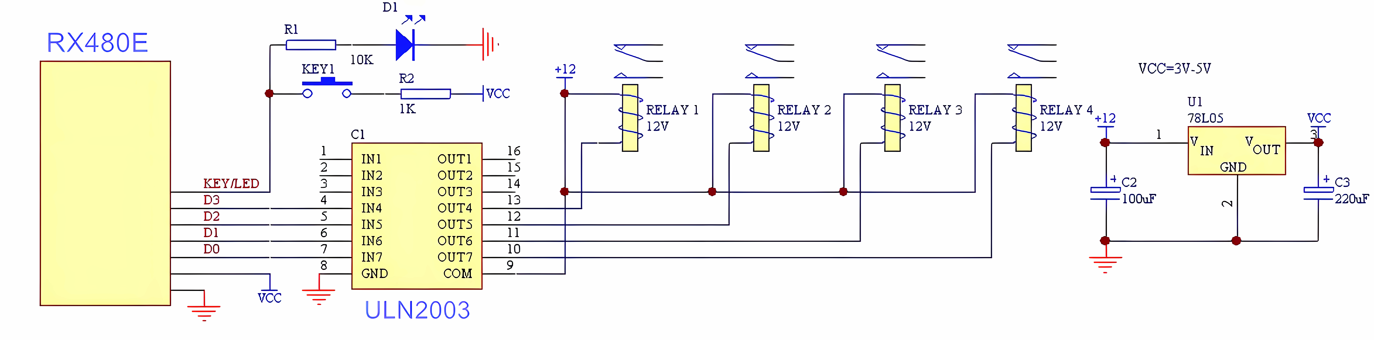
Question 3: Can the four RX480E-868 outputs drive a load directly? How to connect the four outputs to an external transistor or relay?
Answer:
We do not recommend connecting the four RX480E-868 outputs to a load directly. They provide high-level signals in receive mode, and the maximum output current is 10 mA.
The four outputs need a transistor to increase the current before driving a relay, motor, or other load. This wiring requires basic circuit design knowledge. You can also follow our wiring diagram directly.
Question 4: Do I need to pair the transmitter and receiver again after a long power outage?
Answer:
No. Once the transmitter and receiver are paired, they do not need to be paired again after a power outage.
Question 5: Are the four outputs of RX480E-868 high-level or low-level outputs?
Answer:
In receive mode, all four D0-D3 pins of the RX480E-868 are high-level outputs. In transmit mode, the same four pins become low-level signal inputs.
If you need low-level output in receive mode, add a transistor inverting circuit after the four outputs. This wiring requires basic circuit design knowledge.
Question 6: Is Momentary mode the factory default output mode for RX480E-868?
Answer:
No. RX480E-868 has two kinds of mode. Receive mode is the factory default. The output working mode — Momentary, Toggle, or Latching — is not set at the factory. You choose it when you pair the remote control.
To set Momentary mode:
- Power the module on. Two red flashes mean the module is in receive mode. If you see two blue flashes, press the module's Learning button 5 times to go back to receive mode.
- Press the module's Learning button 1 time. The red indicator flashes once and then stays on.
- Press the button on the remote control. The module's red indicator flashes 5 times. Momentary mode is set.